Slower than light
 Probably no one wonders anymore about the possibility of sending information faster than the light speed in vacuum. But, on the other side, does a lower limit exist to signal velocity? And more practically, is the light slowdown really beneficial?
These were the questions we asked ourselves something like ten years ago. Driven by this curiosity, we were among the first research groups in the world to realize how many exciting effects can emerge when an optical wave is slowed down and propagates in the so called “slow-light” regime.
Read more on:
A. Melloni, F. Morichetti and M. Martinelli, “Optical slow-wave structures”, Optics & Photonics News, vol. 14, no. 11, pp. 44-48, Nov. 2003.Two steps forward, one step back: light really slows down !
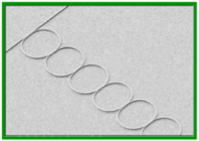 Slowing the light down on a photonic chip is conceptually a simple task. Just make the light propagate back and forth so as to increase the dwelling time inside a guiding structure. That’s all! Optical resonators naturally provide a light recirculation effect and, if properly cascaded, they realize what is commonly known as a coupled resonator optical waveguide (CROW). Propagation in a CROW takes place as in a conventional waveguide, but it is allowed only within certain passing bands where the light is slowed down and the optical power is enhanced accordingly. The power coupling between resonators and the resonant frequency of the resonators are powerful levers that can be used to control the flow of light on a chip, with a variety of possible implications in both linear and nonlinear regime.
(2001-2006) Study first …
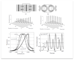 Our experience in slow light started with an in-depth theoretical investigation of optical slow-wave structures. Analytical models and numerical simulators where developed to figure out the main features of slow-light in both the linear and nonlinear regime. In 2003-2004 we led a Working Group of European Action COST P11, whose focus was the comparison of several numerical methods to study the nonlinear response of coupled-cavity optical slow-wave structures. Multi-stability, self-pulsation, optical limiting are only a few examples of peculiar nonlinear effects arising in the slow-light regime. More recently we also investigated CROWs in dynamic regime for stop light, trap light, time reversal and frequency conversion phenomena.
Read more on:
A. Melloni, F. Morichetti and M. Martinelli, “Linear and nonlinear pulse propagation in coupled resonator slow-wave optical structures”, Special Issue of Optical and Quantum Electronics, vol. 35, no. 4/5, pp. 365-379, Mar./Apr. 2003. F. Morichetti, A. Melloni, J. Cap, J. Petracek, P. Bienstman, G. Priem, B. Maes, M. Lauritano, G. Bellanca, “Self-phase modulation in slow-wave structures: a comparative numerical analysis”, Optical and Quantum Electronics, vol. 38, no. 9-11, pp. 761–780, July/Sept. 2006. A. Melloni and F. Morichetti, chapter “Nonlinear Slow Wave Structures“, in Slow Light: Science and Applications, J. Khurgin and R. Tucker (Eds.), CRC Press Taylor & Francis, December 2008. ISBN-10: 1420061518(2007-2011) … play afterwards!
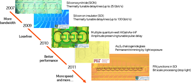
The best technology for slow-light on chip? It is hard to tell, because it strictly depends on the specific application. We played with different photonic platforms in collaborations with international partners with world-leading expertise in the fabrication of integrated circuits (University of Glasgow, Massachusetts Institute of Technology,…).
This is the slow-light roadmap we have followed in the last four years at Politecnico di Milano.
Read more on:
A. Melloni and F. Morichetti, “The long march of slow photonics,” Nature Photonics, vol. 3, no. 3, p. 119, March 2009. A. Canciamilla, M. Torregiani, C. Ferrari, F. Morichetti, R.M. De La Rue, A. Samarelli, M. Sorel and A. Melloni, “Silicon coupled-ring resonator structures for slow light applications: potential, impairments and ultimate limits,” Journal of Optics, vol. 10, no. 10, 104008, (2010) (invited paper).(2007) Continuous or not continuous? That is the delay…
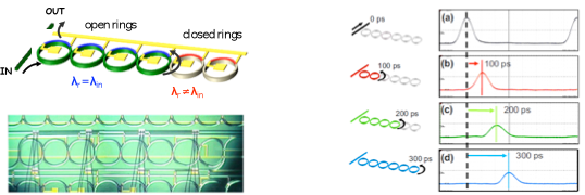
Strange, but true… although a CROW has a discrete number of resonators, it can control the delay of optical pulses with continuity. How to do it is very simple. Just a combination of a digital gating mechanism, where every ring can be either set to a transmissive (open) or reflective (locked) state, and an analog fine tuning of the last open ring of the chain. So, all we need is an individual control of the resonances of the rings, for instance by means of thermal actuators. Our reconfiguration scheme is hitless, that is the CROW can be tuned without halting the data flow, while preserving the signal quality. The first continuously tunable CROW delay line was fabricated in 4.5%-index contrast silicon oxynitride technology and was used to delay a 10 Gbit/s optical signal up to 3 bit-delay with no significant degradation.
Read more on:
F. Morichetti, A. Melloni, A. Breda, A. Canciamilla, C. Ferrari, and M. Martinelli, “A reconfigurable architecture for continuously variable optical slow-wave delay lines”, Optics Express, vol. 15, no. 25, pp. 17273-17282, Dec. 2007. F. Morichetti, A. Melloni, C. Ferrari and M. Martinelli, “Error-free continuously-tunable delay at 10 Gbit/s in a reconfigurable on-chip delay-line,” Optics Express, vol. 16, no. 10, pp. 8395-8405, May 2008. C. Ferrari, F. Morichetti, A. Canciamilla, A. Melloni and M. Martinelli, “Differential polarization delay in coupled-resonator optical waveguides,” IEEE Photonics Technology Letters, vol .21, no. 20, pp. 1541-1543, Oct. 15, 2009.(2008) Happy byte, slow light !
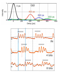 Later in 2008, we demonstrated for the first time the continuous delay of an entire optical byte in a thermally reconfigurable CROW delay line. Successful experiments were performed on single pulses and bit sequences with data rates from 10 Gbit/s to 25 Gbit/s. The achieved 8-bit delay is associated with small fractional losses of less than 1 dB/ bit and moderate pulse broadening, thus preserving signal quality.
Pushing the storage efficiency to the maximum limit allowed by pulse distortion (1 bit/ring), we achieved these results in very compact glass CROWs of only 8 ring with a footprint of 7 mm2. This high storage efficiency enables an easy, reliable, hitless, and relatively low-power consuming management of the delay. A higher storage efficiency is associated to an unavoidable higher pulse distortion.
The maximum achievable delay is currently limited by waveguide loss and injection efficiency into the CROW (see disorder).
Read more on:
A. Melloni, F. Morichetti, C. Ferrari and M. Martinelli, “Continuously tunable 1 byte delay in coupled-resonator optical waveguides “, Optics Letters, vol. 33, no. 20, pp. 2389-2391, Oct. 2008.(2009) Disorder: please, get in line!
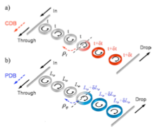 Going very slow needs perfection. Every imperfection in the CROW structure causes some backreflection whose effects scale with the square of the slowdown factor and the square of the disorder parameter.
Disorder can be modeled by exploiting the (old) concept of the characteristic impedance of a periodic slow-light waveguide, this model being applicable to any slow-light structure where the characteristic impedance can be defined. Experiments confirm that pulse distortions due to disorder are one of the main limiting factors for applications based on CROWs.
Read more on:
C. Ferrari, A. Melloni, F. Morichetti, and M. Martinelli, “Disorder in coupled-resonator optical waveguides,” Journal of Optical Society of America B, vol. 26, no. 4, pp. 858-866, Apr. 2009.(2010) Ring vs Photonic Crystals: a fair slow race…
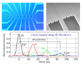 A competition awarding the slowest runner is strange… We were aware of it when we started playing with CROW and photonic crystals delay lines, but what we didn’t suspect was the result.
We compared the frequency- and time-domain response, the delay tunability, the main limits induced by loss, dispersion, and structural disorder, the impact on the transmission of intensity and phase modulated data streams, and even the footprint.
Surprisingly, at the data rate of 100 Gb/s CROWs and photonic crystals behave much more similarly than one would expect. Lower data rates are the preferred domain of CROWs fabricated with large ring resonators, while at data rates in the terabit range, PhCWs remain the leading technology. But at 100 Gb/s the competition is open…
Read more on:
A. Melloni, F. Morichetti, A. Canciamilla, A. Ferrari, L. O’Faolain, T. F. Krauss, and M. Sorel, “Tunable delay lines in silicon phonics: coupled resonators and photonic crystals, a comparison”, IEEE Photonics Journal, vol. 2 , no. 2, pp. 181-194, Apr. 2010 (invited paper)(2011) Learning from the past… travelling-waves widen the bandwidth !
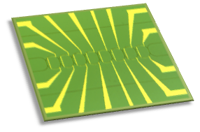 Although any nonlinear interaction is strengthened inside an optical resonator, there are severe bandwidth constraints preventing its practical exploitation for processing broad-band signals.
The reason is that a single resonator is inherently a ‘lumped’ element. To overcome the problem we looked back at the history of optical devices, borrowing the concept of travelling-wave interaction from optical modulators, with the aim to extend the traditional concept of cavity-enhanced four-wave mixing (FWM).
Travelling-wave resonant FWM has been demonstrated in silicon CROWs and was exploited to realize a 630-μm-long wavelength converter operating over a wavelength range wider than 60 nm and with 28-dB gain with respect to a bare waveguide of the same physical length. Compared to a single resonator with the same bandwidth of 80 GHz, a 16 dB efficiency enhancement has been achieved.
Read more on:
F. Morichetti, A. Canciamilla, C. Ferrari, A. Samarelli, M. Sorel, and A. Melloni, “Travelling-wave resonant four-wave mixing breaks the limits of cavity-enhanced all-optical wavelength conversion,” Nature Communications 2, 296, 3 May 2011 A. Melloni, F. Morichetti, and M. Martinelli, “Four-wave mixing and wavelength conversion in coupled-resonator optical waveguides,” J. Opt. Soc. Am. B, vol. 25, no. 12, C87-C97, Dec. 2008.
